- Note:
- The following assumes a strong grasp of binary math and cartesian coordinates.
- Examples use little-endian architecture.
Introduction
Morton coding, first proposed by G. M. Morton in 1966, offers a simple and effective way of "hashing" multi-dimensional integer data into a single value. Using this method, bits from multiple integers are interleaved to produce a single integer. AshTL uses sets of binary "magic numbers" to mask and shift the bits into the correct positions without using temporary variables. To accomplish this, we provide the PCoordXY and PCoordXYZ classes for coordinates, which store the component bits in the correct order for interleaving; fundamentally just a union of a bitfield and an unsigned integer. The number of bits dedicated to each axis is an equal portion of the number of bits in the unsigned integer type. Additionally, we provide the we provide the MortonXY and MortonXYZ types for interleaved coordinates.
The Basic Interleave Process
The most important point to note is that bit-significance is preserved. The significant change in representation is in grouping, from bits grouped by axis to bits grouped by significance. The following 2 images show the process for 16-bit types. AshTL provides both 2D and 3D implementations for 8-, 16-, 32-, and 64-bit types.

In 3D, the number of dimensions does not divide evenly into the bit-size, leaving the remainder unused.
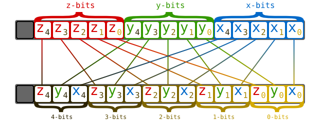
I will discuss the system from here forward assuming a two-dimensional (x, y) coordinate system; the same concepts apply to higher-dimensional representations as well.
Morton Codes & Quad-Trees
It is helpful to think about Morton coding in the context of quad-trees (trees where each node has four children); the two are strongly correlated. Note that AshTL does not provide any quad-tree-based structures, they are simply a helpful concept for understanding the properties of Morton-coded coordinate systems. A Morton code may be considered an address for a node of a quad-tree that represents a grid. Starting at the root of the tree, the address is blank. It represents the entire area of the grid. Each child has a 2-bit address in the range [0b00,0b11].
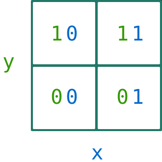
Each child represents a distance 1/2 that of its parent in each dimension. Recall that this is because the pair of bits that represent a parent layer have double the significance of the pair for its child layer. In any pair of bits of the same significance (representing a single layer), the right bit corresponds to the x-axis location, and the left corresponds to the y-axis location. This produces a backward-Z pattern for the node number order.
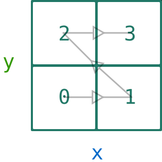
Each of these child nodes also has 4 children, which follow the same rules.
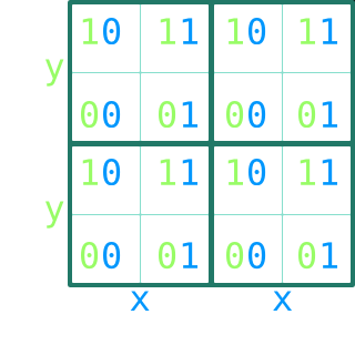
The same backward-Z numbering pattern is reproduced at each layer.
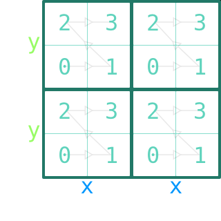
To get the "address" of a node, start from the root with a blank address. With each step from a node to one of its children, append the child's binary number to the right of the binary address string.
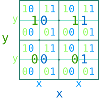
A single layer requires a 2-bit address, 2 layers require a 4-bit address, etc. Multiple adjacent layers may also be considered simultaneously.
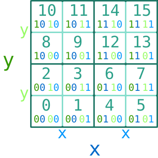
The properties discussed for Morton codes apply to any layer or set of adjacent layers. Combined with the repeated number patterns, this has some important results for grid implementations.


